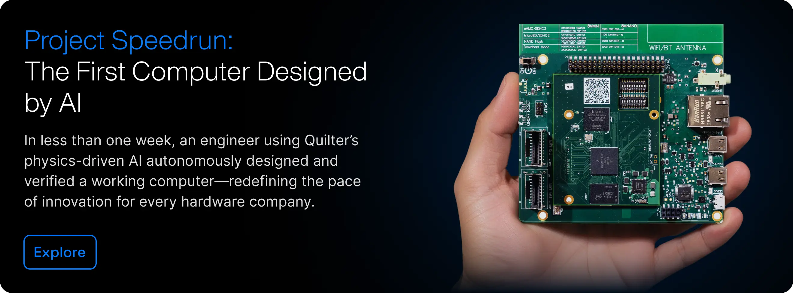
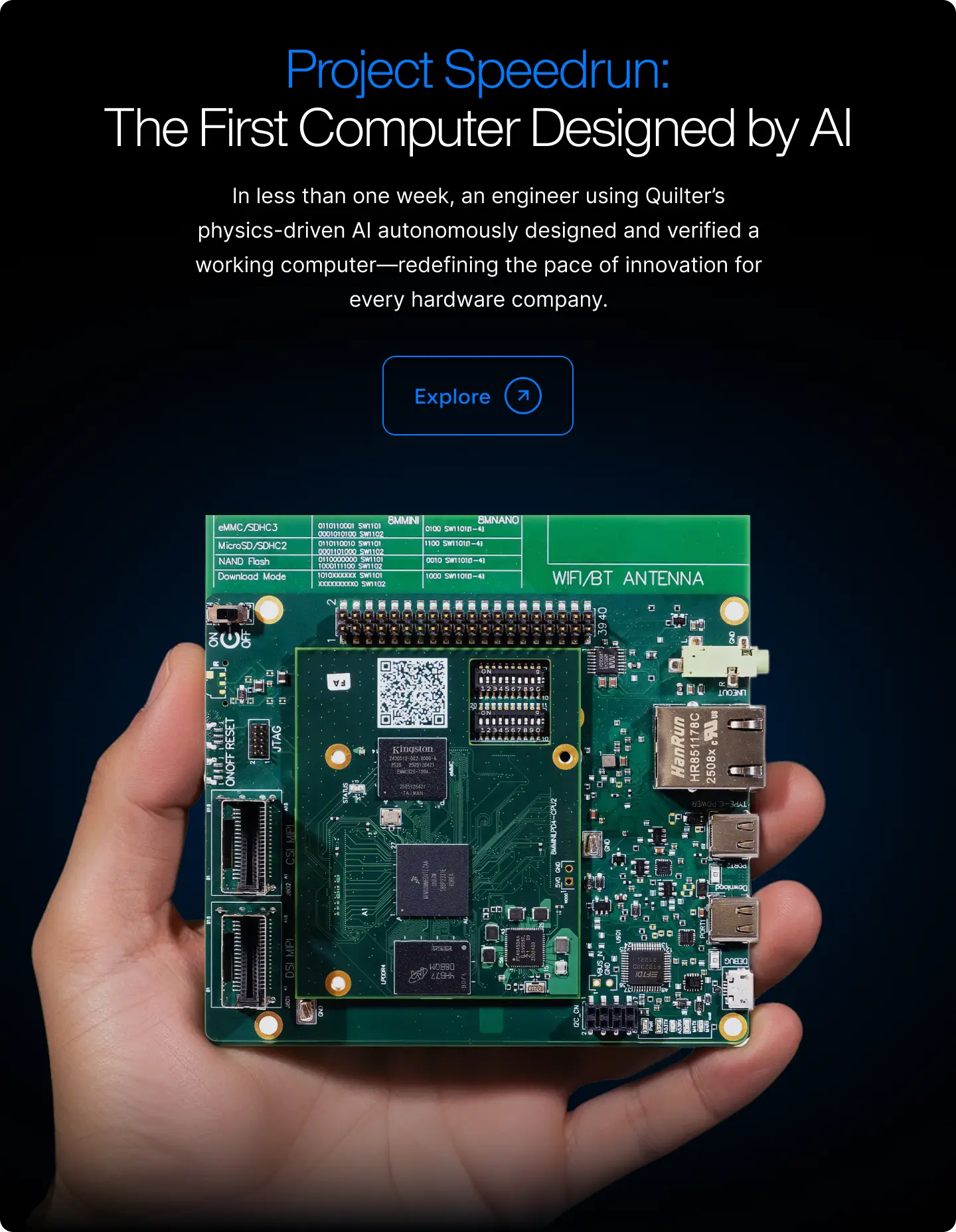
Autorouter

What Is an Autorouter in PCB Design?

An autorouter is a feature built into most EDA (Electronic Design Automation) tools that attempts to automatically route copper traces between component pins based on the schematic netlist. Autorouters use algorithmic approaches — typically maze-solving or grid-based pathfinding — to find valid paths that connect all nets while respecting basic design rules like minimum trace width and clearance. The goal is to reduce the manual effort required to complete trace routing, which is often the most time-consuming phase of PCB layout.

However, traditional autorouters have significant limitations. Because they rely on geometric pathfinding algorithms rather than physics-based evaluation, they produce routes that are electrically valid in a basic sense but often poor from a signal integrity, EMC, and manufacturability perspective. Engineers frequently find that autorouted designs require extensive manual cleanup — rerouting critical signals, fixing impedance violations, improving return paths, and addressing crosstalk — sometimes to the point where the autorouter saves little or no time compared to routing from scratch.

Beyond Autorouting: Physics-Driven AI Layout

Physics-driven AI layout engines represent a fundamental departure from traditional autorouting. Instead of maze-solving individual connections, these tools use reinforcement learning to holistically optimize placement and routing against the full set of physical constraints — impedance, timing, thermal, EMC, and manufacturability — simultaneously. The result is complete, validated layouts that do not require the extensive manual cleanup associated with conventional autorouters, delivering on the promise of automated PCB design that traditional tools have long failed to fulfill.

Other glossary terms

Thank you! Your submission has been received!
Oops! Something went wrong while submitting the form.
There are no available glossary items matching the current filters.
Reset