


Read the Full Series
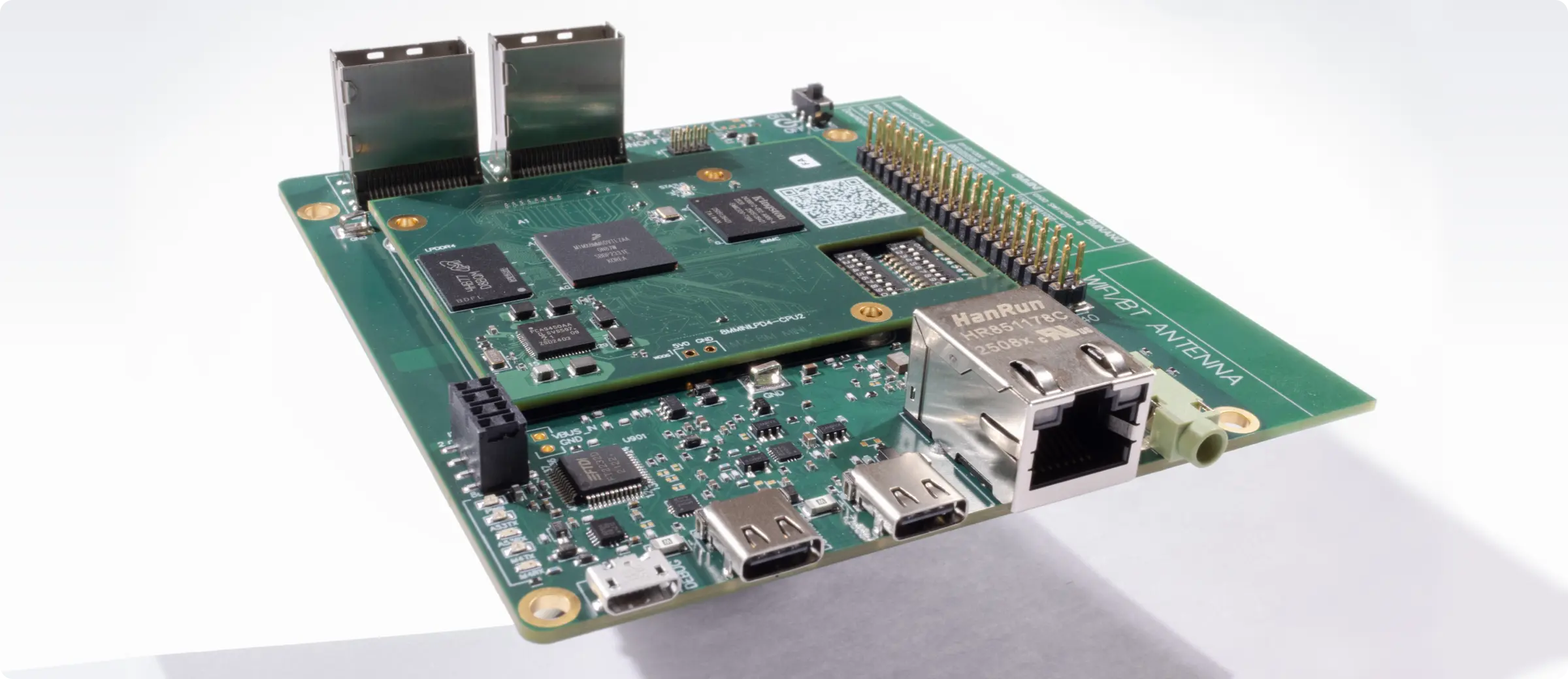
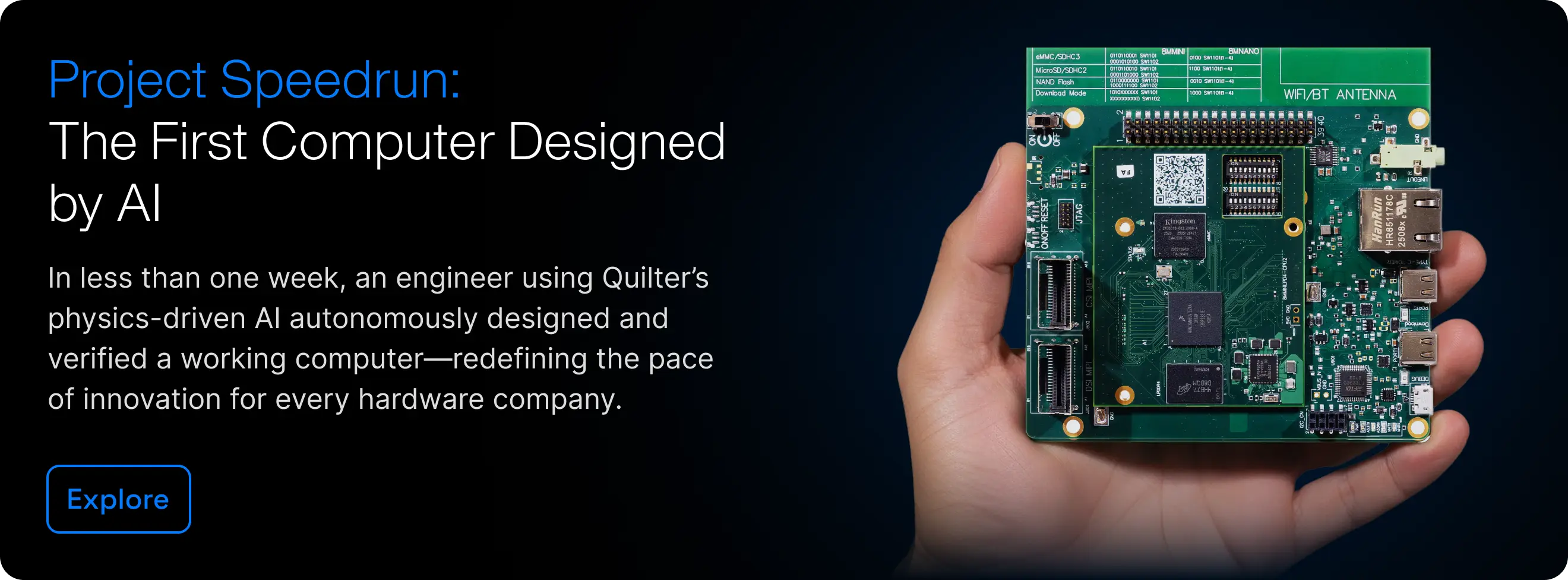
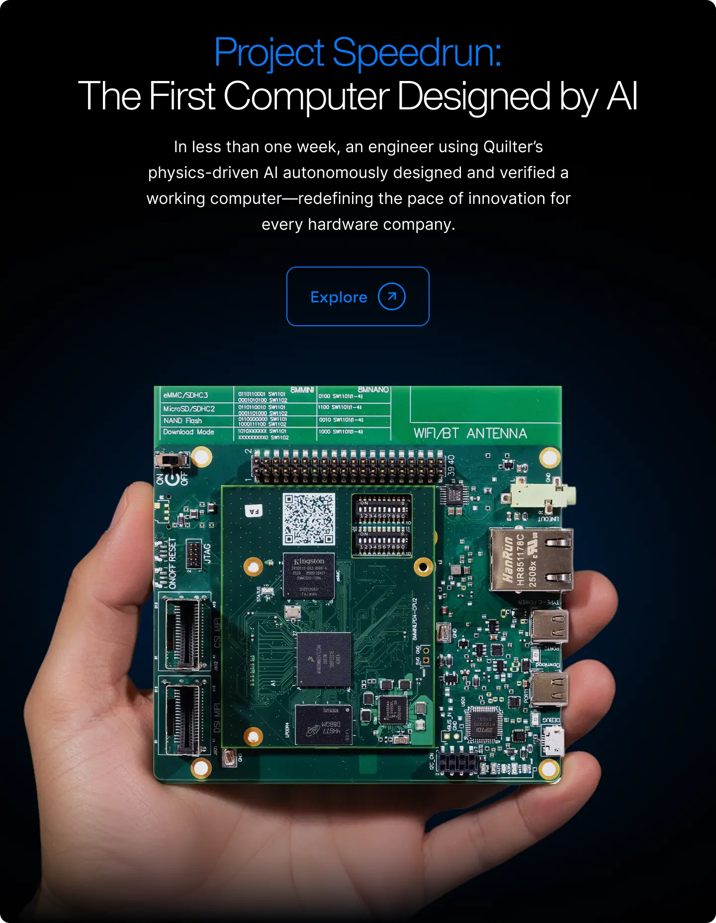
This article is one part of a walkthrough detailing how we recreated an NXP i.MX 8M Mini–based computer using Quilter’s physics-driven layout automation.
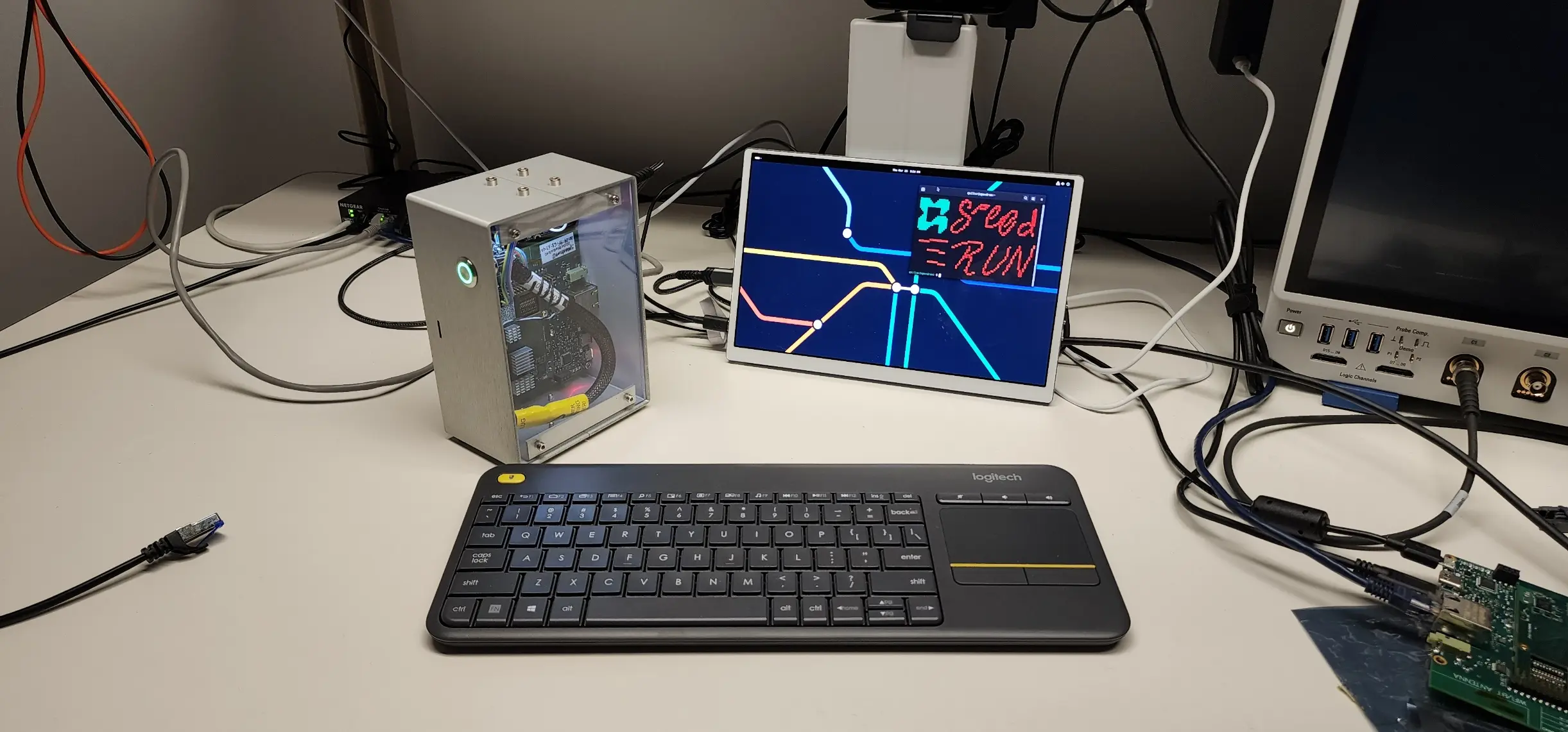
I2C comms
Two devices, the LCD shown above and a trio of sensors in one package, are communicating over the I2C bus at the same time. I captured the SDA (data, red) and SCL (clock, yellow) clock signals while both devices were running.

For fun, I used a Saleae logic analyzer to poke at this signal. We can see the address of the sensor 0x76 and an 8 second delay that I programmed into the sketch. Unsurprisingly, the logic analyzer correctly recognizes these signals as I2C!
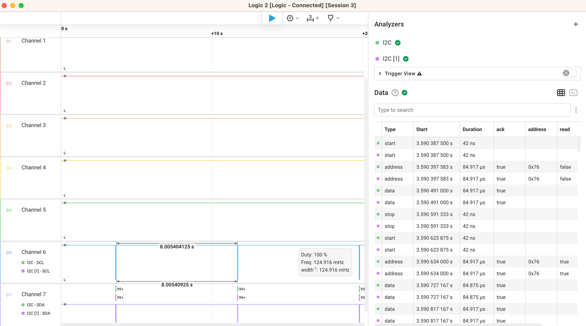
I successfully validated the I2C communication on a Quilter-designed board, confirming proper functionality with two devices connected to the bus.