


Read the Full Series
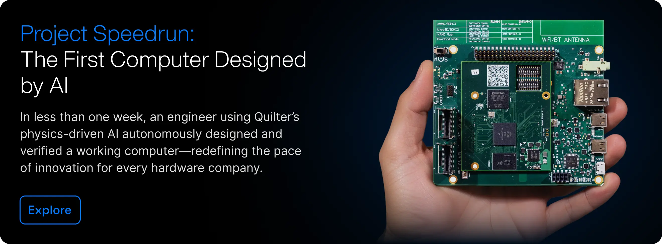
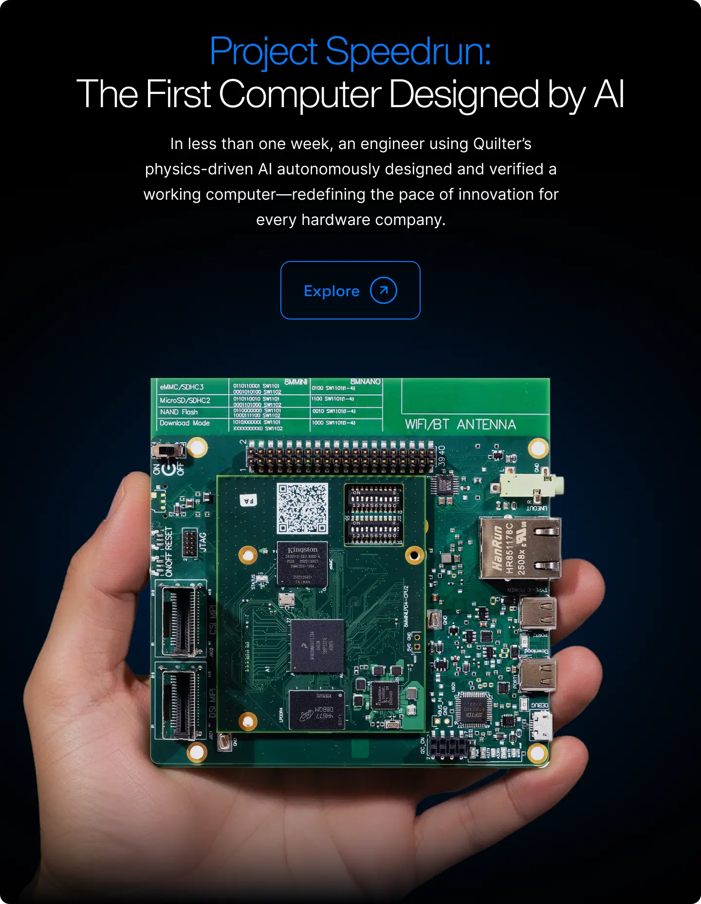
This article is one part of a walkthrough detailing how we recreated an NXP i.MX 8M Mini–based computer using Quilter’s physics-driven layout automation.
Project Speedrun is our challenge to design a complete computer using our physics-driven AI as quickly as possible. This blog series documents how that system was developed and the engineering decisions behind it. Start with the Project Speedrun overview and its results.
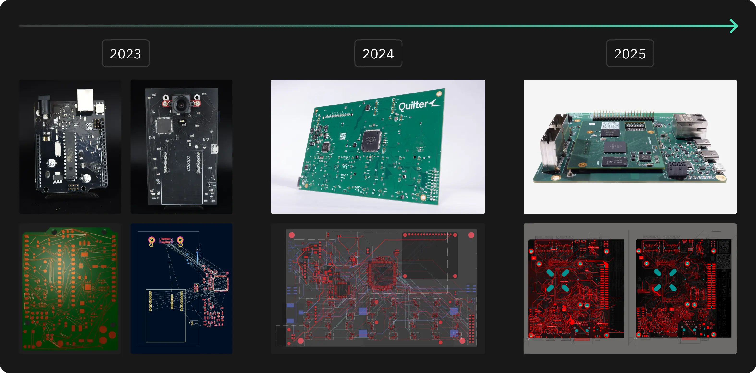
Project Speedrun builds on our ongoing effort to accelerate PCB design by challenging Quilter with increasingly difficult boards. Each cycle gives the team a single direction to push toward and a way to test real hardware to measure progress.
In 2023, we recreated an Arduino Uno. In 2024, we focused on test hardware and completed a multi-sensor FPGA array that simultaneously read and wrote to 32 accelerometers. In 2025, we selected a significantly more demanding target: a complete i.MX 8M Mini–based computer. The NXP i.MX 8M Mini platform is representative of the boards used in aerospace, automotive, industrial control, and safety-critical products.
We chose to evaluate Quilter on a full embedded computer because it exercises every major requirement of modern PCB layout—high-speed memory, mixed-signal interfaces, dense BGA fanout, power distribution, and routing constraints spanning multiple subsystems. If a system can boot Linux, operate peripheral interfaces, run applications, and maintain stable high-speed links, it provides strong evidence that the underlying layout meets the design’s electrical and physical requirements, even if there is still room for improvement.
For baseline comparison, we submitted the same designs to professionals for quotes: the baseboard was estimated at 238 hours of manual layout, and the SOM at 190 hours for a combined 428 hours of layout work over more than 2 months. With Quilter, engineers spent only 38.5 hours on layout–just 12 hours of cleanup the baseboard and 26.5 hours of cleanup the SOM–reducing a quarter-long layout schedule to approximately one week.
Before any of that automation could run, however, the design needed to be prepared so that constraints, intent, and mechanical requirements were clear.
Designing with Quilter – Overview
Getting the most out of any AI system requires a shift in workflow and a shift in expectations. Software engineers who use AI productively have learned how to structure prompts, how to review generated code, and where automation can be trusted versus where it needs oversight. Hardware is no different.
Quilter is designed around the same principle. To be useful, it needs enough information and enough constraints to reason from physics instead of guessing. In practice, that means treating layout as a three-step process:
- Preparation – define the board, constraints, and environment so intent is explicit.
- Running the tool – let Quilter perform constraint validation, placement, and routing.
- Review and cleanup – apply human judgment where it still adds value, then finalize for fabrication.
For Project Speedrun, we followed exactly this structure, starting with preparing the i.MX 8M Mini design so Quilter had the right information to work with.
Preparation
NXP publishes full schematics and CAD files for this platform, originally designed in Cadence Allegro. Our goal was to keep the schematic identical and prove out only the layout portion with Quilter. That gave us a clear baseline: if the board didn't work, it would be due to our layout.
At the time, Quilter did not yet integrate directly with Cadence tools, so the first step was converting the project into Altium Designer. This gave us:
- Schematic sheets we could annotate and structure for constraint generation.
- A board file we could use as the basis for new placement, rooms, and mechanical constraints.
For reasons that will become clear later, the circuitry is split onto two boards:
- A System-on-Module (SOM) with the i.MX 8M Mini processor, LPDDR4, eMMC, and supporting components.
- A baseboard that breaks the SOM out into real-world interfaces: Ethernet, audio, camera, display, storage, and expansion.
With the design in Altium, we could start shaping the schematic and board so Quilter would understand what mattered.
The Schematic
As with any design, everything starts with the schematic. Quilter uses the schematic not just as a connectivity diagram, but as a context for constraint information across the board. The way you structure it directly influences how well the AI can reason about the layout.
A few specific patterns mattered for this project:
.webp)
Bypass capacitors
Quilter automatically detects bypass caps when they are explicitly connected between a component pin and ground. In the i.MX 8M Mini design, we made sure decoupling caps followed this pattern so the tool could reliably identify and treat them as such.
.webp)
Net classes and impedance groups
We used net directives to define classes for power nets, high-speed interfaces, and impedance-controlled signals. By marking these nets in the schematic, we set up a clean way to apply constraints—such as trace width, spacing, and differential impedance—once the design was inside Quilter.
Logical grouping into sub-circuits
For clarity and layout control, we grouped related components into sub-circuits. This could be done either with hierarchical schematics or with blanket directives (for example, grouping everything on a 3.3 V rail or within a power stage). These groupings later became rooms in the PCB, giving us a way to influence floorplanning while still letting Quilter handle detailed placement.
The common thread is that each schematic decision adds structure: it tells Quilter which components belong together, which nets need special treatment, and where the strictest electrical rules apply. That structure is what enables a physics-driven layout instead of a purely geometric one.
The Board
Once the schematic was in good shape, we turned to the board file. This is where mechanical constraints, fixed locations, and floorplanning decisions are captured.
.webp)
We started by defining the board outline and placing all fixed-location components:
- Connectors (Ethernet, USB, audio, M.2, etc.)
- User interfaces (buttons, switches)
- Mechanical features (mounting holes, cutouts, board edges)
These parts must respect enclosures, panelization, and mechanical drawings, so they are treated as hard constraints. Quilter will work around them and will not move or modify them in any way.
.webp)
Next, we used the schematic groupings to generate rooms in the PCB. Each room represents a logical block—such as a power stage, memory interface, or peripheral cluster—that should sit together or in a specific region of the board. We manually placed these rooms to establish the overall floorplan:
- Keep noisy power stages away from sensitive analog sections.
- Place high-speed interfaces along the appropriate board edges.
- Maintain sensible routing channels between the processor, memory, and connectors.
Within those boundaries, Quilter is responsible for the detailed placement of non-fixed components. This balance—engineers own the floorplan, Quilter owns the internal arrangement—gives Quilter the most leeway and chance to succeed without breaking the mechanical or architectural intent of the design.
Good Inputs Make Fast Cycles Possible
Preparing a design for Quilter mirrors the preparation work required for a human layout engineer: clear schematics, defined constraints, and a reasonable understanding of manufacturing. What changes is how that information is used. Instead of engineers doing layout themselves or projects stalling while waiting in a queue for a specialist, your design moves directly into autonomous layout once prep is complete. This groundwork is what accelerates quarter-long cycles to week-long ones.