





Read the Full Series
This article is one part of a walkthrough detailing how we recreated an NXP i.MX 8M Mini–based computer using Quilter’s physics-driven layout automation.
Key Takeaways
You should not avoid 90-degree corners automatically. A corner adds excess capacitance and causes a reflection, and whether that reflection matters depends on the trace geometry and the signal’s rise time or bandwidth. On a 4-mil-wide 50-ohm trace in FR4, a corner adds about 7 fF and keeps return loss below -15 dB until above 100 GHz. Dips in a meander’s time-domain reflectometry (TDR) response that look like corner reflections can come from far-end crosstalk instead. These estimates help find the root cause of reflections; they do not replace pre-layout and post-layout simulation for design sign-off.
- Corner capacitance scales with line width. On a 50-ohm FR4 line, a 90-degree corner adds about 7 fF at 4 mils wide, 100 fF at 60 mils, and 170 fF at 100 mils.
- The simple model matches measurement. On a 60-mil-wide 50-ohm line, the excess capacitance of one corner measured with time-domain reflectometry (TDR) was 95 fF, against the 100 fF the model predicts.
- Dips in a meander’s TDR can be far-end crosstalk. In a microstrip meander, a lossless simulation with the corners removed and only coupling between adjacent legs included reproduced the dips measured at every U-turn.
- The guideline persists for reasons other than signal integrity. Its origins include legacy design rules, acid-trap concerns that may have applied 30 years ago, and layout engineers’ preference for the look of two 45-degree bends.
The Most Important Principle in Interconnect Design
The essence of interconnect design is translating a schematic into a physical layout. When interconnects are not transparent, once connectivity is established, the ONLY thing the interconnects will do is screw things up. They will ONLY add noise. They can never improve the system's performance beyond what the silicon itself is capable of. This is the theme of many of my articles, such as this one.
A simulation based on the schematic using ideal wires as interconnects will always be the best performance you can achieve. This means the guiding principle in interconnect design is to engineer the interconnects to reduce the noise they generate to an acceptable level. This is what design guidelines for interconnects do for us.
Easier said than done.
Legacy Code: Don’t Route with 90-degree Corners
In my 40 years in the high-performance electronics industry, I have encountered many design-guideline recommendations that are either wrong or appropriate in some cases but have been incorrectly generalized to all. Sometimes a design “works” not because of a specific design guideline, but despite it. This is where “myths” arise, which I call legacy code. Reference designs with these misleading guidelines, widely used by the industry, become accepted design practices.
The poster child for legacy code is the design guideline that 90-degree corners should be avoided because they cause reflection noise.
I think one reason this design guideline keeps coming up is the results of a simple experiment many engineers perform.
Delay lines, serpentines, or meanders are a common feature in many designs. They allow a longer delay for the signal in a shorter distance, taking up area rather than just linear length.
I see meander patterns on many evaluation test boards. Here is an example of a 7-leg meander, with each leg 3 inches long, using 20 mil line widths and 10 mil thick dielectric to the adjacent ground plane.
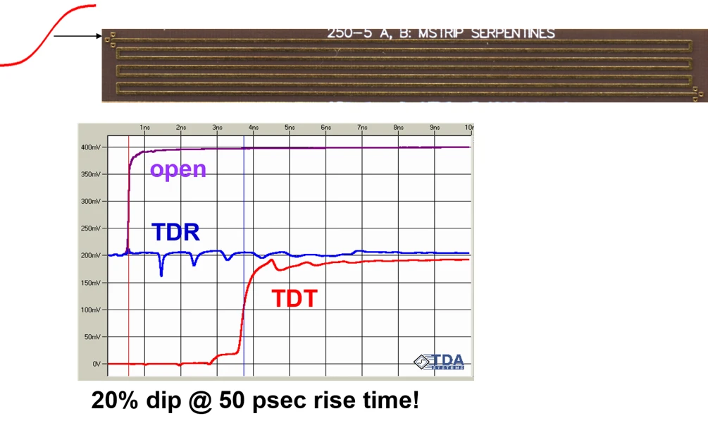
Corners cause reflections, the story goes, because of their excess capacitance. When a signal hits a corner, the capacitive load causes a small negative reflection. In this meander with 6 U-turns, if corners cause reflections, there should be a capacitive dip in the TDR response every 1 nsec. This is 0.5 nsec to travel 3 inches to the corner pair, and another 0.5 nsec for the reflection to return to the TDR source and be recorded.
When the TDR response is measured, the result is shown below, along with the time-domain transmission (TDT) response from a step edge.
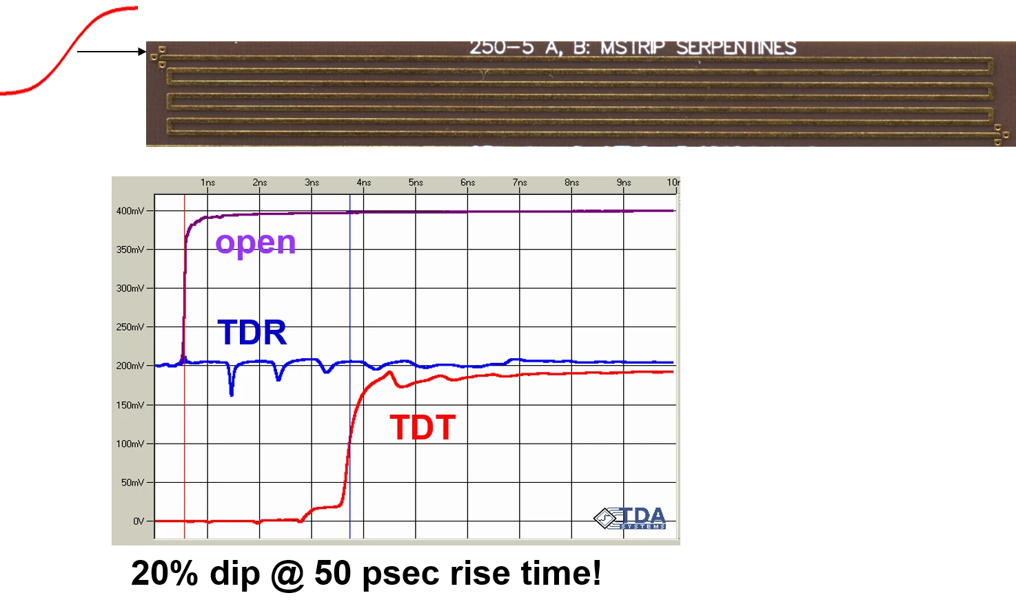
The TDR response is exactly as expected if corners cause reflections. A capacitive dip appears every 1 nsec, corresponding to the two corners at each U-turn. The dips get smaller as the signal travels down the line because losses increase the rise time. The longer the rise time, the smaller the reflected signal from the same capacitive discontinuity.
When most engineers look at these sorts of measurements from test structures, it is a natural conclusion to say that at this 50 psec rise time, which is not untypical of even 5 Gbps signals, going around a 90-degree bend produces noticeable reflection noise and should be avoided.
Proof positive, especially for those prejudiced engineers who say they don’t believe simulations, only measurements. After all, what else could it be?
Apply Engineering Discipline to Analyze All Problems
This is where thinking like an engineer is important when analyzing signal integrity behaviors. There are five important elements to analyzing a signal integrity problem:
- Apply the foundational principles
- Build a virtual prototype in the ideal world and estimate the expected behaviors based on rules of thumb, approximations, and numerical simulations.
- Build a real prototype and apply best measurement practices to verify the behaviors predicted in the ideal world
- Gain confidence in your best simulation and best measurement practices with measurement-simulation correlation.
- Analyze the results from the virtual and real prototypes to understand the root cause of the behaviors and answer the “so what” questions
When we look at the meander, we see a microstrip. Whenever you see a microstrip and adjacent traces, the first thing you should always think is far-end crosstalk. When a signal is launched from the left end into the first leg, it will travel from left to right down the first leg.
At the same time, the second leg is adjacent. There will be far-end crosstalk as the derivative of the step edge, induced in the second leg, also traveling from left to right. This far-end crosstalk will snowball and get larger as the aggressor in leg 1 travels from left to right.
When the far-end crosstalk hits the first U-turn on the far right, it will zip around and travel from right to left back to the TDR source, just as the aggressor signal takes the U-turn and travels from right to left down the second leg. These two signals, the original step and the far-end crosstalk noise pulse, literally pass through each other at the U-turn.
The far-end crosstalk noise travels back to the TDR source and appears as a negative pulse. It arrives 1 nsec after the edge was launched, the first dip.
The same thing happens when the aggressor travels down the second leg from right to left. It induces far-end crosstalk in leg 1 and leg 3. In leg 1, this adds to the first far-end noise, making the first far-end pulse even larger when it is received at the TDR.
The far-end crosstalk in leg 3 makes its way back to the TDR source 2 nsec after launch, and so on. This is illustrated below.

Every 1 nsec, the TDR receives another far-end pulse as a negative voltage dip. And, as the signal propagates, its rise time will increase due to the losses AND the loss at high frequencies into the far-end crosstalk. The far-end crosstalk, as the signal propagates down the meander, will show exactly the same behavior we expect from corners.
Here are two completely different explanations for the same measurement, predicting exactly the same qualitative behavior. How do we distinguish them? … by putting it in the numbers.
Testing Whether Meander TDR Dips Come from Corners or Crosstalk
If you want to verify the behavior of a real-world prototype by simulating its digital twin, you might be tempted to import the layout into a 3D full-wave solver like Simbeor or HFSS, add ports, and simulate the S-parameters. Then look at the S-parameters in the time domain to compare with the measurements.
Unless something is very wrong with your measurement, you will see the same behavior in the simulated TDR response as in the measured response. All you will have confirmed is that this behavior of the small dips is also predicted from the artwork. But you will not gain any insight into what the root cause is.
Philosophically, I do not think we can ever know what is truth in science and engineering. All we can do is get a better approximation to it and use every consistency test we can think of to gain more confidence that we are getting closer to the answer. This means consistency tests are one of your most important tools to verify the root cause and have confidence in your analysis. This is one of the themes in my recent Office Hours Post.
There are many consistency tests you can do to distinguish one explanation or the other:
- Fabricate a real or virtual prototype of the same meander structure in stripline. In stripline, there is no far-end crosstalk, so you should not see any of the dips if they are due to far-end crosstalk, but they will still be present if due to corners
- Fabricate the same microstrip meander (as virtual or real prototype) but with a larger spacing between the legs. If it is corners causing the dips, there will be no change in the TDR response. If it is far-end crosstalk, the dips will decrease.
- Fabricate the real or virtual prototype with rounded or 45-degree bends. If it is far-end crosstalk, the 45-degree bend will not affect the results, but if it is due to corners, the reflections should be reduced.
- Simulate the structure by just turning on coupling to adjacent legs and remove the U-turns in the artwork.
- Calculate the reflected signal from a corner and compare the estimated TDR response to what is measured.
In this example, I simulated the far-end crosstalk using a 2D field solver model of the legs, which included the leg-to-leg crosstalk, but turned the U-turn region into an ideal wire. This eliminated corner reflections and included only the far-end crosstalk effect, in a lossless interconnect. The figure below compares the measured TDR and TDT responses with the simulated TDR and TDT responses.
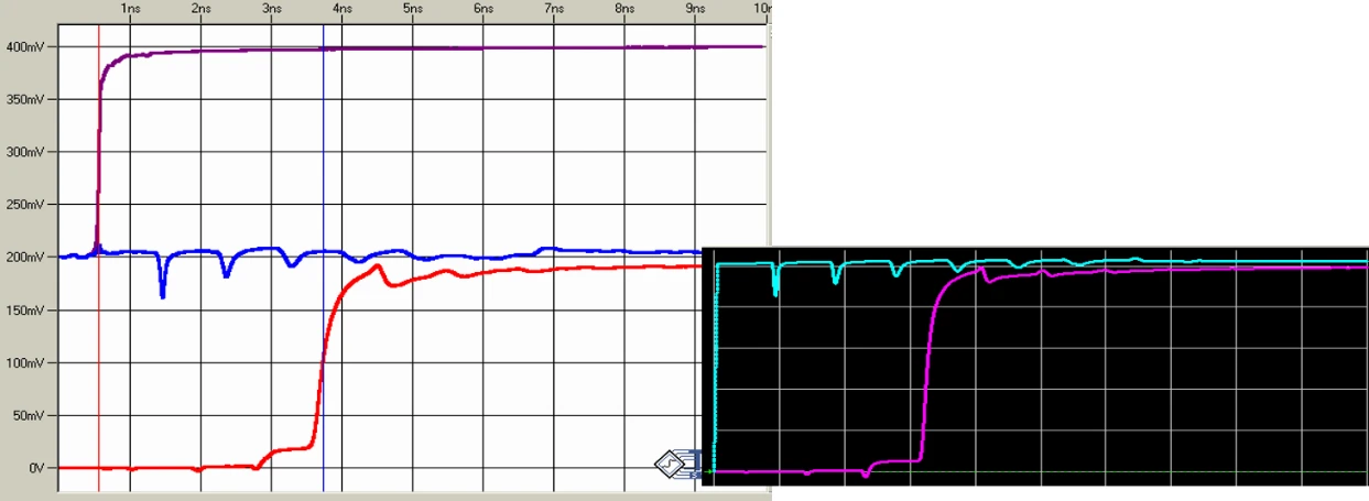
The simulation, which included only coupling between the legs and no interconnect losses, clearly reproduces all the features of the real-world, measured response. The TDR and TDT results match very closely. This specific behavior observed in the TDR and TDT can be predicted just from far-end crosstalk.
Do Corners Cause Reflections?
How do we apply foundational principles to a signal interacting with a corner? I've heard explanations of signal-corner interactions that invoke the idea that electrons have to accelerate around the corner and radiate. I don’t know of any foundational principles behind this interpretation. Instead, I think there is a simpler explanation.
In a uniform transmission line, the signal sees an instantaneous impedance as it propagates. When it encounters a corner, it sees a small excess capacitance because the width at the corner is larger than on the uniform line. This is illustrated here, showing the top view of the signal line, assuming the return path is directly underneath the signal trace:
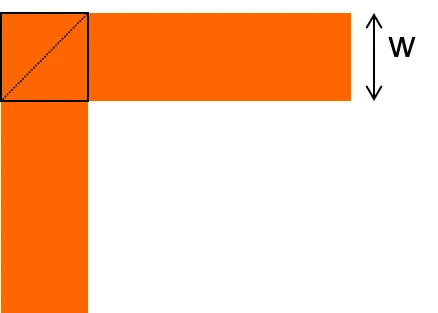
How much extra capacitance is in a corner compared to a uniform line? The total corner capacitance is one square. The excess capacitance is about ½ square. In every uniform 50-ohm transmission line, there is a fixed capacitance per unit length. This depends only on the impedance of the line and the Dk of the material. With a 50 ohm line in FR4, it is about 3.4 pF/inch. This is independent of the line width. If the line width doubles, the dielectric thickness would have to double to keep it at 50 ohms and the capacitance per length stays the same.
The length of 1 square is the linewidth, w [in]. This means the excess capacitance in a corner is roughly ½ x 3.4 pF/in x w[in] = 1.7 pF/inch x w[in] = 1.7 fF x w[mil].
If the line width was 60 mils, and the dielectric thickness to the return plane was 30 mils, the excess capacitance in a corner of a trace would be about 1.7 pF/inch x 0.06 in = 0.1 pF = 100 fF.
Will 100 fF of excess capacitance cause reflection noise? Yes, absolutely.
Measuring the Excess Capacitance of a 90-Degree Corner
We built a simple multilayer board with a uniform 50 ohm line with 60 mil wide traces and four corners, spaced apart. The TDR response, with a 50 psec rise time, was measured. A capacitive discontinuity causes a small dip in the displayed instantaneous impedance. Using a built-in feature of this TDR to extract the excess capacitance, we measured the excess capacitance in one corner. Here is the measured response showing the four corners and the four capacitive dips:
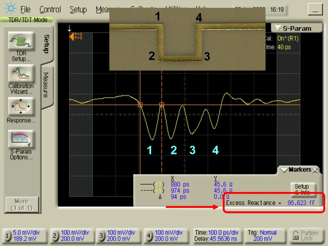
The excess capacitance measured for this corner is shown in the lower right of the screen as 95 fF, pretty close to our 100 fF estimate.
The first "so what" is that corners absolutely cause reflections, and we can easily measure them. The estimated corner capacitance using this simple model is a very good approximation of what we measured.
But the second important “so what” is the scaling this model suggests. The capacitance in a corner is not an intrinsic property of a corner. It scales with the line width as long as the line is a 50-ohm line. You cannot take a specific example, like this 60 mil wide trace which shows an excess capacitance of 100 fF, and generalize that all corners have 100 fF of capacitance.
In fact, with a 50-ohm line width of 100 mils, the capacitance of a corner would be 170 fF, while a narrow 4-mil-wide 50-ohm line would have an excess capacitance of only 7 fF.
In addition, the impact on step-edge reflections from a corner also depends on the rise time of the incident signal. The shorter the rise time, the larger the reflected amplitude. This TDR response can be simulated very easily using a discrete ideal capacitor as the discontinuity in an otherwise uniform line.
Should We Avoid Corners?
In a PCIe Gen 4 channel operating with NRZ at 16 Gbps, the UI is 62 psec. The rise time is about 15 psec, and the signal's Nyquist bandwidth is 8 GHz. In a 224 Gbps channel operating with PAM4, the UI is 9 psec and the rise time is about 4 psec. The signal’s Nyquist bandwidth is about 56 GHz.
The simulated TDR response of a 90-degree corner in a 50 ohm 4-mil wide line with a capacitance of 7 fF is shown below for the case of a PCIe gen 4 signal and a 224 Gbps signal.
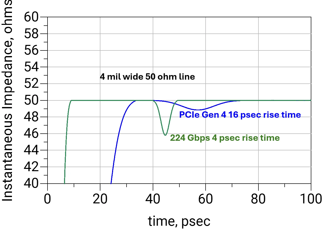
While this shows the larger reflected response from a shorter rise-time signal, is this reflection too much? Should we be worried about a corner for 224 Gbps signals?
The Frequency Domain Sometimes Provides More Insight Than the Time Domain
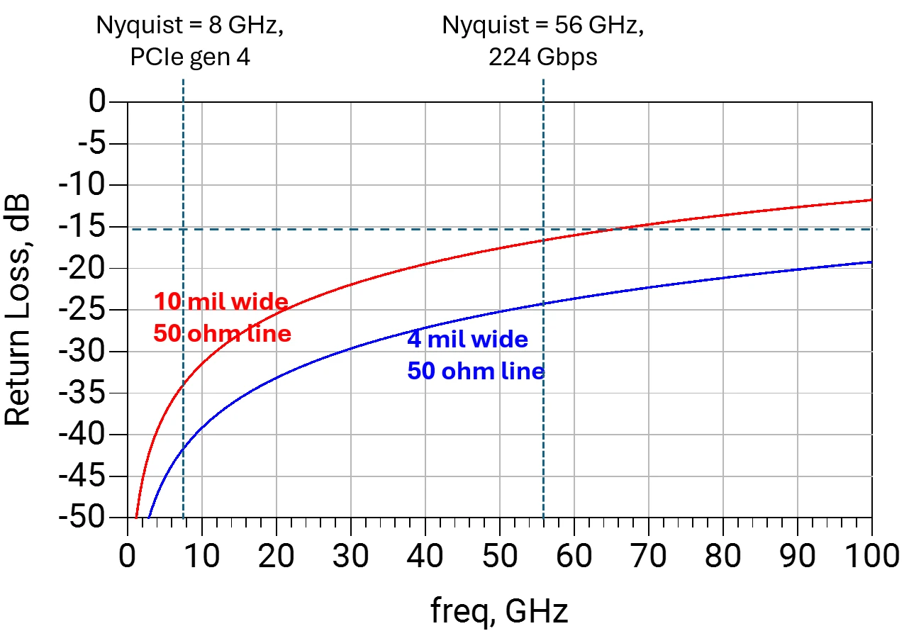
One of the metrics to describe the properties of an interconnect is the S-parameters. When evaluating the impact of a reflection, we look at the return loss, S11. If the return loss is less than -15 dB, the impact on the transmitted signal, S21, will be less than 0.1 dB, which is insignificant. This is why many connector specs use -13 dB as a requirement for the return loss. Return loss isn't what is important; its impact on insertion loss is what matters.
Here is the simulated return loss from a corner in a 10 mil wide 50 ohm line and a 4 mil wide 50 ohm line compared with the -15 dB threshold at the two Nyquist frequencies of 8 GHz and 56 GHz.
So When Should You Worry About PCB Trace Corners?
Now we have a way of making a value judgment about the impact of a corner in a few specific cases. A corner with a 10 mil wide trace will potentially create a return loss above -15 dB at about 60 GHz. If your signal bandwidth is greater than 60 GHz, you probably should worry about corners. If your line width is 4 mils, a corner will create a return loss greater than -15 dB above 100 GHz.
These estimates should not be used to sign off on a design. Use them to offer insight into the root cause of problems. Anyone designing a 224 Gbps channel will always be performing pre-layout and post-layout simulations. You will invariably see return loss above the -15 dB threshold of concern. But, before you cast blame on corners in your interconnects, look for other sources of reflection noise. It is unlikely to be corners.
Why do hardware engineers view corners with such distaste? Part of the reason is legacy code. Armed with the skills to analyze the impact of a corner, you can make a well-qualified engineering judgment about whether corners will cause a signal integrity problem in your design.
I also hear that another reason corners are viewed unfavorably is that the 90-degree bend is an acid trap. When the copper is etched off, a drop of the acid bath can adhere to the corner by capillary forces, and the contamination continues to corrode it. This might have been true 30 years ago, but if your fab vendor warns you against corners because of acid traps, your fab vendor does not have a very good process. Find another fab vendor.
Finally, when I talk to layout engineers, they tell me that two 45-degree bends make a corner look better on a board. It is pleasing to the eye. This may be the real reason layout engineers are taught to avoid 90-degree bends.
When there are so many very real signal integrity problems to understand and avoid, we don’t need another one adding noise and contaminating well-considered signal integrity design guidelines. This is why it is important to understand the foundational principles and how to apply them to analyze the important signal integrity problems you will absolutely encounter as you drive toward higher data rates.
As I often say, there are two kinds of engineers: those who have signal integrity problems and those who will.
Conclusion
The problem with the internet at our fingertips is not that there is not enough information available; it is that there is too much information, and much of it is worse than useless; it is sometimes wrong or misleading. Scattered among the content are gems of wisdom and insight that can help you accelerate up the learning curve and become a more effective engineer.
Every time you encounter a design guideline, ask: what problem is this guideline trying to reduce? Then apply your foundational principles and skills in analysis to evaluate the value of this design guideline in reducing the problem. And, for every design guideline, always watch out for the whack-a-mole effect, the law of unintended consequences.
In this series of posts, I will offer some clarity on what is high-value information and what is noise. The really cool thing about science and engineering is that it is not about opinions; it is about evidence. In the field of signal integrity and high-performance system design, it is about applying the foundational principles of signal integrity to understand the behavior of signals on interconnects and how to reduce how much they will screw up the signals.
Frequently Asked Questions
Should You Avoid 90-Degree Corners in PCB Traces?
It depends on the trace geometry, the signal bandwidth, and the criterion you use to judge the reflection. A 90-degree corner does cause a reflection, because it adds a small excess capacitance of about 1.7 fF per mil of line width on a 50-ohm line in FR4. A practical criterion is return loss: below -15 dB, the effect on the transmitted signal (S21) is about 0.1 dB or less. By that measure, a corner on a 4-mil-wide 50-ohm trace stays below -15 dB until above 100 GHz, while a corner on a 10-mil-wide trace crosses it at about 60 GHz.
How Much Capacitance Does a PCB Trace Corner Add?
A 90-degree corner adds about half a square of the trace’s capacitance. A uniform 50-ohm line in FR4 has about 3.4 pF/inch regardless of its width, which works out to roughly 1.7 fF of excess capacitance per mil of line width. The value scales with width: about 7 fF on a 4-mil trace, 100 fF on a 60-mil trace, and 170 fF on a 100-mil trace. On a 60-mil-wide 50-ohm test line, the corner capacitance extracted from a TDR measurement was 95 fF, close to the 100 fF estimate.
Why Does the TDR Response of a Serpentine Trace Show Dips?
In a microstrip serpentine (meander), a dip at every U-turn looks like a corner reflection, but it can come from far-end crosstalk between adjacent legs. The crosstalk builds along each leg and returns to the TDR source at the same intervals that corner reflections would. In the seven-leg example in this article, a lossless 2D field-solver simulation that removed the corners and kept only the coupling between legs reproduced the measured TDR and TDT dips, so the dips cannot automatically be attributed to the corners. Building the same structure in stripline, where there is no far-end crosstalk, separates the two causes.
Are 45-Degree Bends Always Better Than 90-Degree Bends?
They are an improvement when the 90-degree corner’s reflection is large enough to matter in your design. Replacing a corner with 45-degree or rounded bends should reduce its reflection, which is why changing the bend style is one of the consistency tests for telling corner reflections apart from far-end crosstalk. Whether that reduction matters depends on the line width, the signal bandwidth, and whether return loss stays below -15 dB. This article does not include a measured comparison of bend styles. Layout engineers often prefer two 45-degree bends because they look better on the board, which may be the main reason the 90-degree rule persists.
Are 90-Degree Corners Safe for 224 Gbps PAM4?
The single-corner estimates in this article are useful background, but they are not enough to approve a 224 Gbps channel. A 224 Gbps PAM4 signal has a Nyquist frequency of about 56 GHz and a rise time of about 4 psec. A corner on a 4-mil-wide 50-ohm trace keeps return loss below -15 dB until above 100 GHz, so corners are unlikely to be the main source of reflection noise in such a channel. Wider traces add proportionally more corner capacitance and leave less margin. Signing off a 224 Gbps channel still requires pre-layout and post-layout simulation of the full channel.
Are 90-Degree Corners Acid Traps?
With a good fabrication process, they are not a concern. Acid traps may have been a problem 30 years ago, but a fab vendor that warns against corners because of acid traps does not have a very good process.
Sources
Bogatin, Eric. “Bogatin’s 20 Rules for Engineers.” Signal Integrity Journal, January 14, 2020. https://www.signalintegrityjournal.com/blogs/4-eric-bogatin-signal-integrity-journal-technical-editor/post/1539-bogatins-20-rules-for-engineers.
Bogatin, Eric. “Measuring Only Board-Level Power Rail Noise May Be Misleading.” Signal Integrity Journal, September 20, 2022. https://www.signalintegrityjournal.com/articles/2790-measuring-only-board-level-power-rail-noise-may-be-misleading.
Bogatin, Eric. “Office Hours with Prof Eric Bogatin, 2026-09-28.” Prof Eric Bogatin (Substack), September 28, 2026. https://profericbogatin.substack.com/p/office-hours-with-prof-eric-bogatin-325.
Bogatin, Eric. “Should You Worry About 90 Degree Bends in Circuit Board Traces?” Signal Integrity Journal, April 13, 2021. https://www.signalintegrityjournal.com/articles/2104-should-you-worry-about-90-degree-bends-in-circuit-board-traces.
IEEE 802.3 Working Group. “IEEE P802.3dj 200 Gb/s, 400 Gb/s, 800 Gb/s, and 1.6 Tb/s Ethernet Task Force.” Accessed October 7, 2026. https://www.ieee802.org/3/dj/index.html.
Shlepnev, Yuriy. “Validation of Bend Models with Measurements.” Signal Integrity Journal, September 22, 2021. https://www.signalintegrityjournal.com/blogs/7-voice-of-the-experts-signal-integrity/post/2258-validation-of-bend-models-with-measurements.
About Dr. Eric Bogatin
Dr. Eric Bogatin is Technical Fellow at Quilter, the Physics-Driven AI platform for PCB Layout Automation, and advises its physics and engineering teams. He is a professor in the Department of Electrical, Computer, and Energy Engineering (ECEE) at the University of Colorado Boulder, where he teaches graduate-level signal integrity courses and the Senior Design Lab Capstone Course. He is the former technical editor of Signal Integrity Journal, a Fellow with Teledyne LeCroy, and the Dean of the Teledyne LeCroy Signal Integrity Academy. He is the author of 18 books on signal integrity and electronics, including Signal and Power Integrity: Simplified (Pearson, 3rd edition, 2018), Principles of Power Integrity for PDN Design: Simplified (2017), and Practical Guide to Transmission Line Design and Characterization for Signal Integrity Applications (2020). He holds a B.S. in physics from MIT and an M.S. and Ph.D. in physics from the University of Arizona.


.webp)