


Read the Full Series
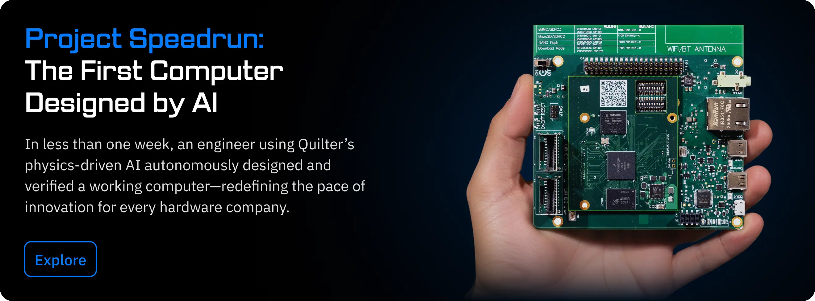
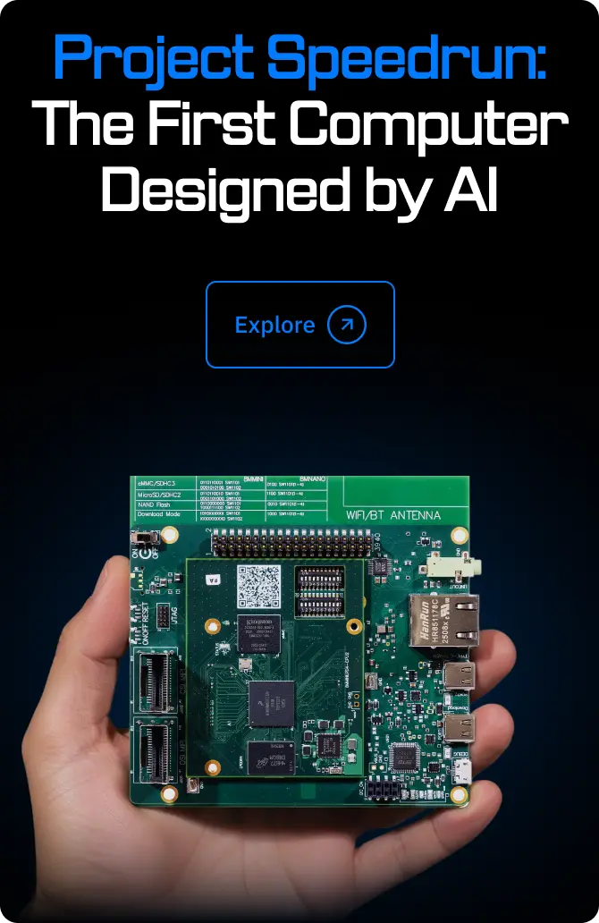
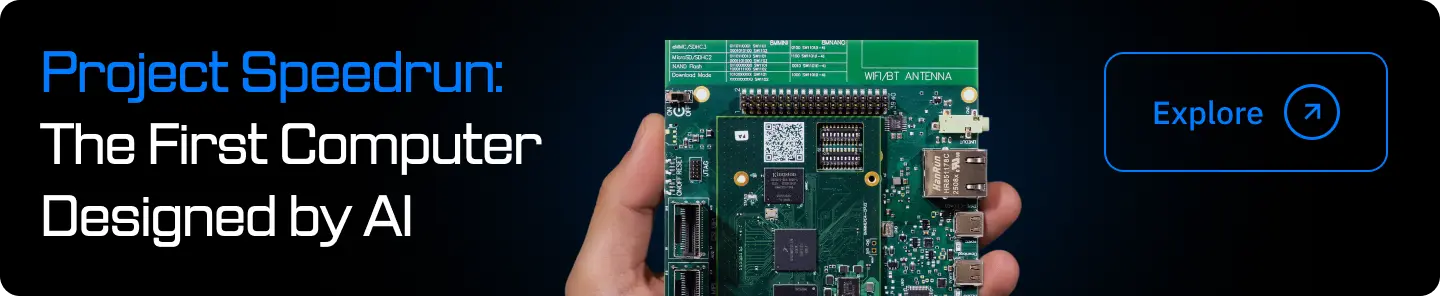
This article is one part of a walkthrough detailing how we recreated an NXP i.MX 8M Mini–based computer using Quilter’s physics-driven layout automation.
If you’ve ever spent hours cleaning up after an autorouter, you know that “automatic” doesn’t always mean “accurate.” As PCB complexity grows, the gap between what traditional tools can automate and what your design actually needs is only widening. In this post, we’ll break down why most PCB layout generators hit a wall and how AI-driven approaches like Quilter are redefining what accuracy really means in modern board design.
What Makes a PCB Layout Truly “Accurate”?
What is the most accurate PCB layout generator?
There is no single universally “most accurate” PCB layout generator for every design. Accuracy depends on your constraints (high-speed, RF, power integrity), board complexity (layers, BGAs, density), and how completely you encode intent (rules, stackup, critical-net requirements). That said, the most accurate outcomes consistently come from tools that can optimize placement and routing together while validating real electrical and physical behavior, not just checking rule compliance. This is where AI PCB layout systems that are physics-driven, like Quilter AI, are pulling ahead of traditional autorouters.
Accuracy is bigger than “passes DRC”
A board can pass DRC and still be wrong in the ways that matter: marginal eye diagrams, noisy rails, unstable return paths, weak decoupling effectiveness, or manufacturability edge cases that show up as yield loss later. In practice, layout accuracy is multi-dimensional:
- Electrical accuracy: Signal integrity, power integrity, EMI/EMC behavior, crosstalk control, return-path continuity, and impedance control.
- Manufacturing accuracy: Routing and via choices that match your fab’s capabilities, yield expectations, and stackup realities (not just theoretical constraints).
- Intent accuracy: Layout decisions that reflect schematic intent and system goals, like which nets are truly critical, what must be clustered, and which tradeoffs are acceptable.
Critical nets expose “rule-only” automation
Traditional routers can route a net. The hard part is routing the net correctly in context.
A few examples where “routing done” and “routing accurate” diverge quickly:
- Impedance-controlled nets: The geometry might match a width rule, but transitions, reference plane changes, and via stubs can still hurt performance.
- Differential pairs: Matching length is not enough if coupling varies, return paths are discontinuous, or the pair is forced through noisy regions.
- Return paths and reference continuity: The router sees copper clearance. Physics sees loop area, plane splits, and where current actually returns.
- Power delivery and decoupling: A design can meet clearance rules while creating poor current loops or ineffective capacitor placement relative to the IC pins.
True accuracy is holistic by default
The biggest insight is simple: layout is not “placement, then routing.” Layout is a coupled optimization problem. Placement decisions create routing feasibility, and routing constraints should shape placement. When tools treat these as separate steps, the board inherits compromises that no amount of post-routing cleanup fully fixes.
That’s why the phrase “most accurate pcb layout generator” is evolving. Engineers are not asking for prettier traces. They’re asking for correctness you can trust across electrical behavior, manufacturability, and intent.
Here’s Why Traditional Autorouters Hit a Wall
Autorouters have improved. Constraint systems have improved. Yet many teams still use autorouters only for “easy” nets and then manually route the parts that actually determine success. That is not because engineers enjoy hand routing. It’s because of architectural limits in how classic autorouting works.
1) Autorouters inherit placement problems and cannot fix them
Most autorouters start after placement is “done,” even though placement is rarely final. If a connector is slightly off, or a BGA is rotated incorrectly, or decoupling is scattered, the autorouter will do its best inside a bad starting state. It might technically complete routes, but it cannot globally improve the layout.
In dense designs, the wrong early placement creates:
- Congestion channels that force long detours
- Excessive layer swaps and via count
- Broken return paths and awkward plane crossings
- Unnecessary coupling between sensitive nets
At that point, the router is not designing. It is coping.
2) Rule-based systems do not understand intent
Traditional autorouters are fundamentally rule-driven. They are excellent at following what you explicitly encode. But PCB layout accuracy often depends on what you did not, or could not, fully encode:
- Which nets are most sensitive to discontinuities
- Which regions are electromagnetically noisy in practice
- Which tradeoffs matter more, fewer vias vs shorter length vs cleaner return paths
- Which placement adjacency is essential for system behavior
Engineers carry this intent in their heads and in tribal knowledge. Rule-based automation can only act on what is formally expressed in constraints. That is why “PCB autorouter limitations” persist even in premium EDA suites.
3) Local routing decisions create global damage
Many routers solve routing as a sequence of pathfinding problems: net-by-net, region-by-region, with heuristics for congestion. That produces an output that can look reasonable while still being globally suboptimal.
Common symptoms:
- “Spaghetti” routes that wander to avoid short-term conflicts
- Overuse of vias to escape local congestion
- Length matching achieved by ugly meanders in poor locations
- Sensitive nets routed through places a human would avoid
The core issue is global optimization. Routing is not independent for each net. Every decision changes the search space for everything else.
4) Cleanup becomes the hidden tax
Ask a seasoned PCB designer what they think about push-button autorouting, and you will hear a consistent story: it can be helpful, but it creates follow-on work.
Typical cleanup tasks include:
- Rerouting critical nets to restore return paths and reduce noise coupling
- Removing unnecessary vias and layer swaps
- Replacing length-tuning artifacts with cleaner topologies
- Fixing manufacturability issues that arise from dense escape patterns
- Revisiting placement because routing exposed earlier mistakes
That is why the “automatic” label often feels misleading. The output is not the finish line. It is a draft.
The wall is not “routing is hard”
Routing is hard, but modern compute can route. The wall is that accurate PCB design requires integrated decisions across placement, routing, and physics. Classic autorouters treat physics as a set of constraints and checks after the fact. Accuracy demands more than that.
How Does AI Change the Game for PCB Layout?
AI PCB layout is not “a faster autorouter.” The meaningful shift is that modern systems can treat PCB layout as the coupled optimization problem it really is: placement plus routing plus physics-aware evaluation, solved together.
This is the thesis behind Quilter: physics-driven PCB design using reinforcement learning to generate complete PCB layouts that work, not just layouts that route.
1) Simultaneous placement and routing enables global optimization
When placement and routing are solved together, the system can make tradeoffs that traditional flows cannot. For example:
- Move a component slightly to eliminate an entire via field
- Rotate an IC or connector to reduce length and layer swaps
- Pull decoupling into a tighter loop region to improve current return behavior
- Allocate routing channels so critical nets stay short and clean
This is the core reason AI-driven layout can be more accurate. It is not forced to accept placement as immutable. It can search the design space more holistically.
2) Intent awareness starts from the schematic, not from guesswork
Accuracy depends on recognizing what matters early. Quilter identifies considerations like bypass capacitors, impedance-controlled nets, and differential pairs up front for your review. That matters because it shifts the workflow from “route everything and hope” to “design with intent, then execute.”
This is a key difference from rule-only approaches. Instead of asking the engineer to anticipate every subtlety, the system helps surface what is likely critical so you can confirm constraints and priorities early.
3) Physics validation is not optional, it is part of the loop
A traditional autorouter can satisfy spacing and length rules and still produce fragile electrical behavior. Quilter’s positioning is different: candidates undergo an extensive physics design review so you can evaluate functionality, not just geometry.
Think of it this way:
- Rule checking answers: “Is this legal?”
- Physics-driven evaluation answers: “Will this work reliably?”
For high-speed interfaces, sensitive analog, and mixed-signal boards, that distinction is the difference between “passed DRC” and “shipped product.”
4) More candidates changes how teams design
One of the quiet advantages of AI layout is not just quality. It is abundance. If you can generate multiple viable layouts in hours, you can:
- Compare tradeoffs across stackups or manufacturers
- Try multiple floorplans and connector placements
- Choose the best candidate based on real metrics, not intuition
- Iterate more before a board ever goes to fab
This is why AI PCB layout is becoming a strategic advantage. It turns layout from a bottleneck into a search process where you can explore, evaluate, and pick the best.
5) Quilter fits how engineers actually work
Adoption fails when a tool demands a new universe. Quilter works with existing workflows: upload native projects from Altium, Cadence, Siemens, or KiCad, define outline and constraints, pre-place connectors, set your intent, then review candidates and export back into your EDA environment for final polish, DRC, and fab output.
The aim is not to replace engineering judgment. The aim is to remove the repetitive, time-consuming parts so engineers can spend time on the high-value decisions.
What Results Can You Expect from AI-Driven PCB Layout?
Engineers evaluating “the most accurate pcb layout generator” usually want proof in two forms:
- Visual proof: does it look like a board a great designer would ship?
- Metric proof: does it reduce vias, shorten critical routes, improve return paths, and decrease risk?
Below is a practical way to present the comparison on your blog. Use the same board, same constraints, same stackup, then compare a top autorouter output (example: Altium Situs) vs Quilter AI output.
A metrics scorecard that decision-makers care about
Publish a table that summarizes measurable improvements. Keep it honest by labeling it as an example from a representative design and noting that results vary by board complexity, constraints, and starting placement.
Example improvement scorecard (illustrative, varies by design)
Metric
Typical autorouter outcome
AI-driven outcome (Quilter-style)
Why it impacts accuracy
Total via count
Higher
Lower
Fewer discontinuities, better manufacturability, less stub risk
Critical net length
Longer detours
Shorter, more direct
Better timing margin and lower loss
Layer swaps on sensitive nets
Frequent
Reduced
Cleaner return paths, fewer impedance transitions
DRC violations after routing
Often needs cleanup
Fewer issues on candidates
Less rework, faster to final
Congestion hot spots
Common
Reduced
More stable routing, easier ECOs
Power loop tightness (qualitative)
Depends on placement
Improved by co-optimization
Better decoupling effectiveness and rail stability
If you want a bullet-list version for skimmers, use this:
- Fewer vias and layer swaps on the nets that drive reliability
- Shorter, cleaner topologies for timing-critical or impedance-controlled paths
- Less cleanup work because placement and routing are optimized together
- More candidates to compare, so you pick the best layout instead of accepting the first routable one
What engineers tend to notice first
Even before measurement, experienced designers spot the same themes when comparing classic autorouting to AI layout:
- The AI layout looks like it was designed, not just routed
- Routing channels are cleaner and more intentional
- Critical nets have priority baked in, not bolted on
- The design feels easier to review and easier to ECO
That “reviewability” matters. A layout that is physically coherent is easier to validate, easier to modify, and less likely to hide subtle failures.
Let’s Talk About Integrating AI Layout Into Your Workflow
The fastest way to kill interest in AI layout is to imply engineers must abandon their toolchain. They will not. The practical path is to integrate AI into existing EDA flows with minimal friction.
Works with your existing CAD and review process
Quilter supports uploading native projects from major ecosystems, then returning files in the same format so your team can keep using the tools you trust for final checks, documentation, and release.
A typical workflow looks like this:
- Upload your existing project (native CAD files)
- Define the board outline and constraints
- Pre-place connectors
- Set routing priorities, net classes, impedance constraints, and keepouts
- Generate multiple candidates
- Review candidates transparently
- See which constraints are satisfied
- Identify what is done vs what needs refinement
- Export back to your EDA tool
- Run your standard DRC
- Polish the layout
- Generate fab files
This approach reduces adoption risk because it does not ask teams to trust a black box blindly. It creates a reviewable pipeline.
Why this reduces schedule risk, not just labor
AI layout is often pitched as speed. Speed matters, but accuracy is the real lever. When layout quality improves earlier, you reduce:
- The chance of a respin
- The time spent on layout cleanup
- The number of late-stage ECOs caused by routing constraints
- The bottleneck of limited expert PCB layout bandwidth
Quilter’s “Iterate More” value is especially relevant here. When you can try multiple candidates quickly, you can choose the best physical solution earlier and avoid locking in compromised placements.
Enterprise considerations: security and mission-critical support
Technical decision-makers care about compatibility, but they also care about reliability, support, and risk management. If you are writing for aerospace, defense, semiconductor validation, or high-stakes consumer programs, emphasize:
- Review transparency and deterministic handoff into the team’s native environment
- Support and documentation resources
- The ability to keep engineers in control of constraints and intent
The message is straightforward: AI does not remove rigor. It enables more rigor sooner because you can evaluate more options.
Ready to See the Difference for Yourself?
If you are evaluating the most accurate pcb layout generator, do not judge by “can it route.” Judge by whether it can co-optimize placement and routing while validating the physics that actually decides success.
- Try Quilter for free using the Free Version
- Book a demo for a technical walkthrough with your real constraints and board types
Helpful next resources to link in your CMS:
- Product Overview
- Technology (Physics-driven PCB design approach)
- Workflow (How to go from schematic to layout faster)
- Documentation and Help Center
Accuracy is not a checkbox. It is the outcome of global optimization plus physics-aware decisions. Traditional autorouters will keep improving, but their core architecture keeps them boxed in. AI-driven layout changes the architecture of the problem, and that is why it is becoming the future of PCB design accuracy.


